Neutral
Earthing transformers are normally provided in 3-phase system, which is
without neutral and earth fault protection.
Neutral earthing transformer is having zig-zag (interstar) winding to
achieve the required zero phase impedance. In addition an auxiliary
winding can also be provided to meet the requirement of auxiliary power
supply.
ONAN / ONAF cooling with conventional pressed steel radiators. The range
includes up to 33 KV systems and as per the site requirements.
A Earthing ( zigzag) transformer is a special purpose transformer with
a zigzag or 'interconnected star' winding connection, such that each
output is the vector sum of two phases offset by 120?. Its applications
are for the creation of a missing neutral connection from an
un-grounded, 3-phase system to permit the grounding of that neutral to
an earth reference pointand also harmonic mitigation, as it can suppress
triplet (3rd, 9th, 15th, 21st, etc.) harmonic currents, to supply
3-phase power as an autotransformer (serving as the primary and
secondary with no isolated circuits), and to supply non-standard
phase-shifted 3-phase power.
Nine-winding three-phase transformers, typically have 3 primaries
and six identical secondary windings which be used in zigzag winding
connection as pictured. As with the conventional delta or wye
winding configuration three-phase transformer, a standard
stand-alone transformer containing only six windings on three cores
can also be used in zigzag winding connection, such transformer
sometimes being referred to as a zigzag bank. In all cases, six or
nine winding, the first coil on each zigzag winding core is
connected contrariwise to the second coil on the next core. The
second coils are then all tied together to form the neutral and the
phases are connected to the primary coils. Each phase, therefore,
couples with each other phase and the voltages cancel out. As such,
there would be negligible current through the neutral point, which
can be tied to ground.
Each of the three "limbs" are split into two sections. The two
halves of each limb have the equal number of turns and they're wound
in opposite directions. With the neutral grounded, during a phase to
ground short fault, a third of current returns to the fault current
and the remainder must go through two of the three phases when used
to derive a grounding point from a delta source.
If one phase, or more, faults to earth, the voltage applied to each
phase of the transformer is no longer in balance; fluxes in the
windings no longer oppose. (Using symmetrical components, this is
Ia0 = Ib0 = Ic0.) Zero sequence (earth fault) current exists between
the transformer’s neutral to the faulting phase. The purpose of a
zigzag transformer in this application is to provide a return path
for earth faults on delta-connected systems. With negligible current
in the neutral under normal conditions, providing the defective load
will be automatically disconnected in a fault condition, an
undersized transformer may be used only as short time rating is
required (i.e. the transformer can only carry full rated current
for, say, 60 s). Impedance should not be too low for desired maximum
fault current. Impedance can be added after the secondaries are
summed to limit maximum fault currents(the 3Io path).
An application example: A combination of Y (wye or star), delta, and
zigzag windings may be used to achieve a vector phase shift. For
example, an electrical network may have a transmission network of
110 kV/33 kV star/star transformers, with 33 kV/11 kV delta/star for
the high voltage distribution network. If a transformation is
required directly between the 110 kV/11 kV network an option is to
use a 110 kV/11 kV star/delta transformer. The problem is that the
11 kV delta no longer has an earth reference point. Installing a
zigzag transformer near the secondary side of the 110 kV/11 kV
transformer provides the required earth reference point.
|


 1
1 2
2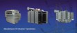 3
3